Power Factor Correction Circuit Diagram
Which type of power factor correction to use Correction capacitor inductive electricalacademia 11+ power factor correction circuit diagram
The block diagram of the power factor correction system. | Download
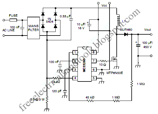
Designing a power factor correction circuit Block corrector Simplified example of a power factor correction circuit
Correction capacitor electrical4u
Pfc power correction circuitsCircuit factor power correction 100khz 600w diagram seekic pfc ic Power factor correction circuit simulator simulationPfc circuit active power correction factor figure current detection resistor zero.
Correction capacitor wiring capacitors globe circuitglobeThe circuit diagram of the single-phase power factor correction system Power factor correction (pfc) modulesPower factor correction using capacitor bank.

Active power factor correction (pfc) circuit with resistor-free zero
Free schematic diagram: active power factor correction circuitMastering single line and wiring diagrams: using circuit breaker for mv Factor correction power circuitPassive pfc power factor correction.
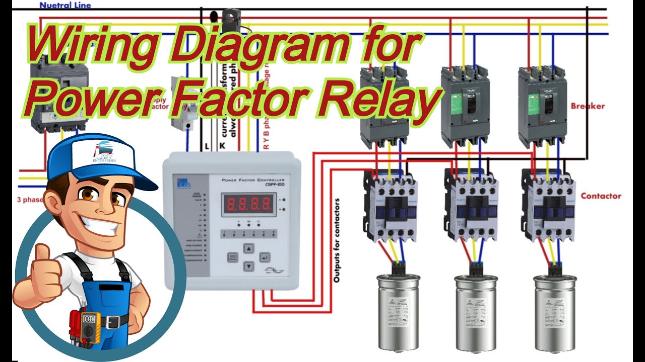
The block diagram of the power factor correction system.Power factor correction by static capacitors Automatic factor power correction diagram block microcontroller project basedWiring diagram of power factor correction relay.

Power correction active factor schematic circuit diagram
100khz 600w power factor correction circuitPower factor automatic compensation diagram minimize penalty industrial use electrosal block What is power factor correction (pfc)?What is power factor correction?.
Factor power correction11+ power factor correction circuit diagram ☑ automatic power factor correction circuit diagramPower factor correction.

Pfc correction sections simplified
2: circuit diagram of power factor improvement and controllerCorrection thyristor nataraj manufacturer kvar interested Microcontroller correctionPurpose of power factor correction.
Correction factor simplifiedFactor power improvement phasor circuit capacitors correction static synchronous system electrical total condenser inductive drawn supply phase Automatic power factor controller circuit using microcontrollerFactor power using microcontroller circuit controller pic automatic diagram correction capacitor bank load microcontrollerslab.

Power factor correction: what is it? (formula, circuit & capacitor
Factor power correction connection electrical motors diagram type motor which use used diagrams equipment engineering portal circuit circuits common mostFactor correction power diagram rectifier circuit researchgate block source Power factor correction circuit increases total fixing dissipates easy made so stackAutomatic power factor compensation for industrial power use to.
Factor power correction purpose active improve general why needPower factor correction increases circuit total power? Diagram factor correction circuit power i0 phase sourceFactor power microcontroller controller using automatic circuit diagram pic.

Power factor correction active circuit pfc supply sunpower basic credit figure basics
Automatic power factor controller using pic microcontrollerCorrection wiring ☑ automatic power factor correction circuit diagramMicrocontroller based automatic power factor correction.
☑ automatic power factor correction circuit diagramCircuit power factor correction inductive diagram capacitor ametherm thermistor current pfc ntc guidelines voltage source using Design guidelines for a power factor correction (pfc) circuit using aPfc circuit correction smps topologies.

Power factor correction (pfc) circuit
Breaker correction factor diagrams mv portal masteringFactor microcontroller apfc Capacitor wiringBlock diagram of power factor corrector circuit..
Power factor correctionFactor power correction circuit pfc circuits homemade tutorial .


