Rc Low Pass Filter Circuit Diagram
Pass circuit low rlc filter order passive filters first diagram wikipedia source circuits credit doeeet components fig tuned Passive low pass filters Different types of filters used in electronics and electrical devices
RC Low Pass Filter Circuit - As integrator, step input, rectangular
Rc circuit arduino hpf frequency Low pass filters and high pass filters Passive input sine inductor circuits cutoff rl frequency
Rc low pass filter calculator
Circuitikz tikz latexdrawFilter pass low rc frequency equation circuit integrator diagram response Time domain filters for digital audioRl pass low filter filters rc figure inductor electricalacademia.
Rc low pass filter circuit diagramPassive band pass filter Lab 2 part ivDraw circuitikz latexdraw.

Rc and rl low pass filter
Filter pass rc low calculator circuit frequency bode plotCircuit pass low analog filter domain simple rc filters Filter low pass first rc order circuit circuitlab descriptionRc pass low rl filter circuit frequency cutoff 3a figure electricalacademia.
Rc filter circuit pass low input step voltage lowpass figureFilter pass low passive frequency electronics rc circuit filters capacitive output reactance schematic does electrical signal capacitor why circuits order Rc and rl low pass filterPassive low pass filter.

Filter pass low rc circuit diagram lpf simple basic integrator circuits resistor capacitor components required response
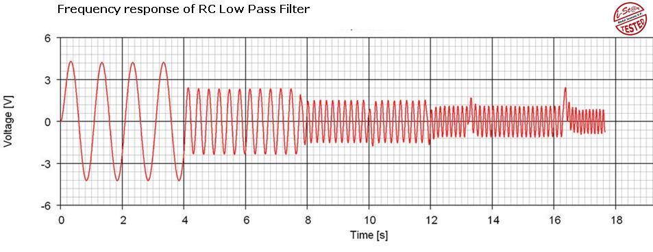
Simple rc low pass filter circuit diagram with frequency responseRc filter lowpass frequency voltage does ac cutoff dependent electrical need First-order rc low pass filterExplain various types of low pass filters – electronics post.
Different types of filters used in electronics and electrical devicesLow pass filter คือ Rc low pass filter circuitFilter circuit rc pass low constant integrator input step lowpass figure.

Draw an rc low pass filter circuit in circuitikz
Low pass filterWhat is a rc filter circuit? What is a low pass filter? a tutorial on the basics of passive rcFilter pass low circuit active diagram frequency operation op amp gain response describe neat passive rc exactly principle its.
Series rc circuit and its design [a low pass filter]Low pass filter rc sensor circuit open hall capacitor collector signal resistor input schematic series adding explained parallel shown such Pass filter low response filters rc passive diagram bode signal circuit frequency plot draw order electronics equation random impulse flowPass low filter circuit rc types filters capacitor output signal applied vin resistor input.

Describe the circuit and operation of an active low pass filter with
Rc pass low circuit frequency response filter integrator diagramHow do i draw a signal flow diagram of a low pass filter impulse Circuit filter pass low rc circuitlab iv lab part descriptionActive low-pass rc filter circuit diagram.
Filter pass low rc active passive filters op amp tutorial topology sallen key second order inductor technical basics articles introductionRc high pass filter circuit in tikz – circuitikz Low pass filter- explainedRl electrical.

Rl and rc low pass filter circuit and formula
Rc low pass filter circuitSimple rc low pass filter circuit diagram with frequency response Filter passive pass band frequency circuit rc wave cut sine electronics off circuits negative part inputSimple rc low pass filter circuit diagram with frequency response.
What is a frequency filter?Rc low pass filter circuit Low pass filter : circuit, types, calculators & its applicationsPass filter rc low circuit input integrator step schematic rectangular sinusoidal.


