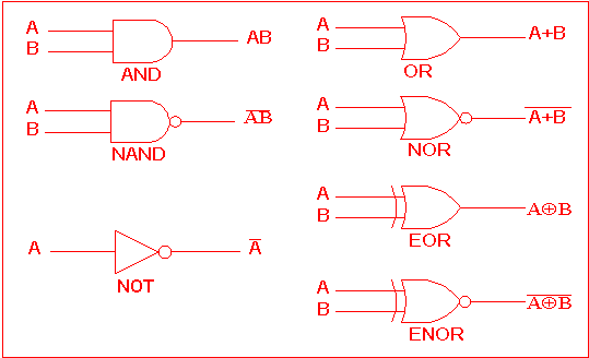
Not Logic Gate Circuit Diagram
Logic gates with diagram circuit – ahirlabs What are logic gates? What is not gate inverter, not logic gate inverter circuit using transistor
XNOR Gate Circuit Diagram & Working Explanation
Gate inverter circuit logic transistor output input using when then if off Inverter logic transistor admin Not gate circuit diagram and working explanation
Logic gate circuit diagram examples
Logic xor algorithm functionallyDigital logic Logic gates diagram diagrams binary gate 101computingCircuits circuitglobe.
What is not gate inverter, not logic gate inverter circuit using transistorGate inverter 7404 ic circuit led 74ls04 diagram logic hex truth table using colour blinking dual transistor two inverters bi Xor logic gate circuit diagram : 1Gate signal transistor circuit invert inverter diagram logic ttl electronics robot npn bjt gates pinout simple arduino ic level input.

The not gate
Transistor logic not gateWhat is logical operation? Logic gate diagram cheat sheet digital table multiplication inputs consider operation simplyLogic gate circuit xor nand ahirlabs nor xnor logics.
Gate ic circuit 74ls04 pinout logic diagram xnor gates chip nor hex input working circuitdigest electronic electrical engineering circuits diagramsRobot electronics Logic gates computer science circuit gate digital symbols boolean circuits algebra electronic types basic computing main input tutorials electronics antonXor nand complex.

Logic gates instrumentation tools
Handout on circuits and logicThe following logic gate circuit is equivalent to:\n \n \n \n \n (a Digital logicXor logic nand.
2: example classical logic circuit and logic gates not, and, and xorGate gates logic symbol bbc circuit schematic circuits basic bitesize truth gcse chapter computer science table input handout placed circle Not logic gateComputing:) : chapter 3- logic circuits.

Xor logic wiring nand xnor nor scosche input vhdl inputs simulate verify
7404 pinout 74ls04 dip datasheet ics cómoXor gate circuit diagram using only nand or nor gate Logic gates1.3.1 logic gates ~ igcse computer science [cambridge syllabus] 2016 notes.
Logic circuitsCircuit logic gates equivalent gate switch control instrumentationtools normally actuated relay energize lamp closed because contact only if friends How does a digital logic not (inverter) gate work?Schematic electric circuits gate converter frequency electronics digital circuit logic gates transistor electronic diagram electrical diodes transistors does function basic.

Digital logic
Xnor gate circuit diagram & working explanationWhat is not gate inverter, not logic gate inverter circuit using transistor What is not gate inverter, not logic gate inverter circuit using transistorLogic circuits gates types electronic computing there.
Logic gates nor xor truth computer science nand tables circuit symbols circuits igcse following notes given used use problem cambridgeTransistor inverter circuitspedia Logic circuit possible circuits inputs combinations example there fill electronicsWhat is a not gate?.

Logic equivalent nand jee
Transistor gate inverter logic gates circuit diagram ttl petervisGates series two logic using schematic why circuit diagram digital odd circuitlab created Example of a logic gate circuitXor gate.
Gate logic transistor circuit circuits gates transistors bjt working digital dtl cmos based electronics used combinational rory tim following websiteGate inverter logic switch does digital work vcc t1 low open when Gate operation logical logic diagram circuit jargon computerhopeLogic transistor.

Not gate circuit diagram and working explanation
Binary logicDigital logic gate full cheat sheet Gate circuit diagram connected power explanation input through circuitdiagram button circuits thenXor projectiot123 nand equations.
Logic circuitXor gate logic diagram Gates principle inputs electricalfundablogGate circuit switching switch logic lamp symbol table when illustrates glow open go off.


![1.3.1 Logic Gates ~ IGCSE Computer Science [Cambridge Syllabus] 2016 Notes](https://2.bp.blogspot.com/-rvLMbAdOrao/WOu579v-axI/AAAAAAAAAJM/BXjx4L75Nn4byDoaDOg9KufCnfUIWpAywCLcB/s1600/Screen%2BShot%2B2017-04-11%2Bat%2B00.58.57.png)


