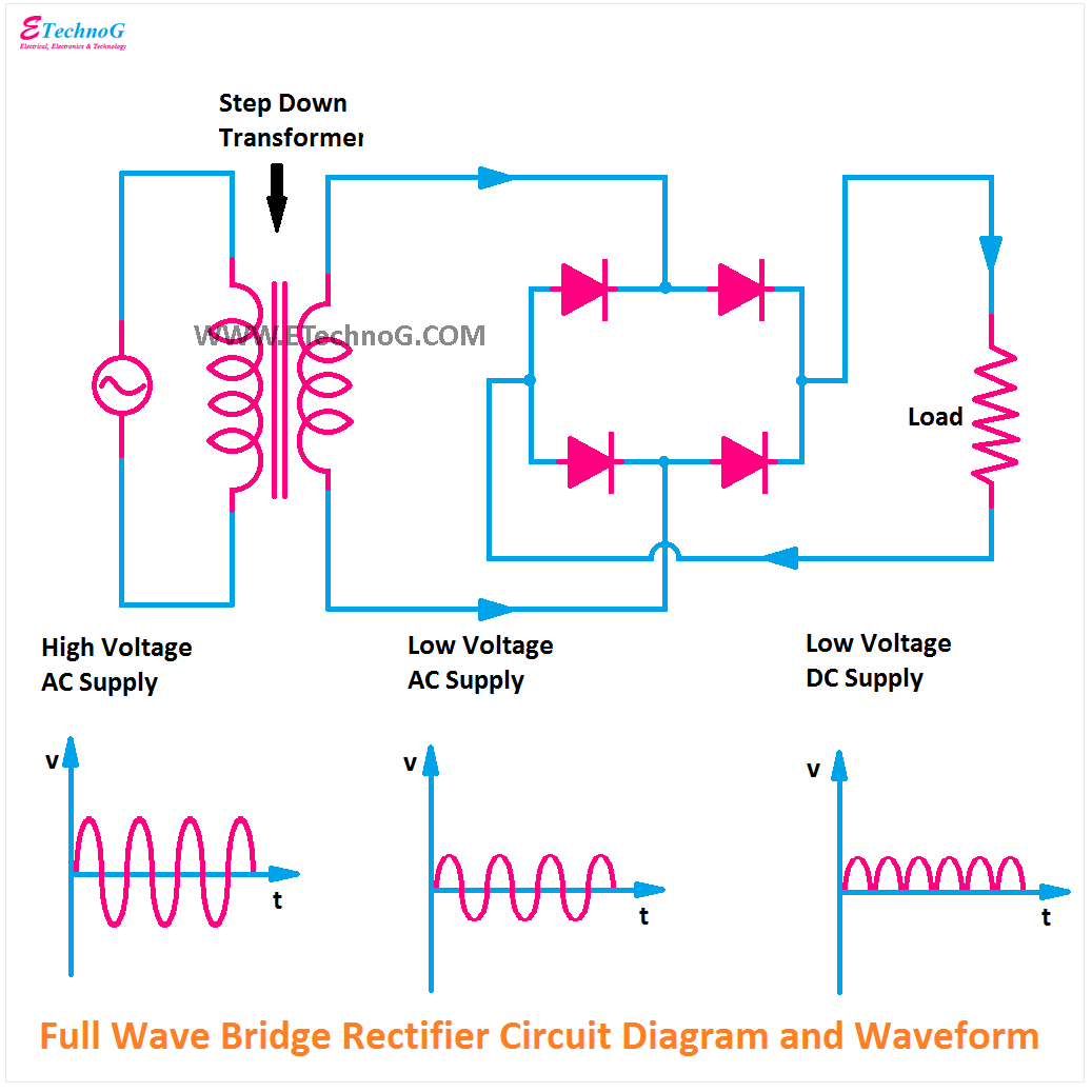
Full Bridge Rectifier Circuit Diagram
Rectifier capacitor ripple Full wave bridge rectifier – circuit diagram and working principle Rectifier wave circuit filter without diagram bridge capacitor tapped diodes center four board below using circuitdigest circuits type choose
Bridge Rectifier: Functions, Circuits and Applications - Utmel
Full wave bridge rectifier Zener bridge rectifier circuit diagram What should i consider when choosing the right diode…
Half wave & full wave rectifier: working principle, circuit diagram
Rectifier wave bridge operation half input working current biased cycle d3 animation diodes tutorial positive reverse during forward d4 d1Rectifier transformer diodes consists resistor Rectifier capacitor wiring diode resistor unwantedFull wave rectifier circuit diagram (center tapped & bridge rectifier).
Bridge circuit wave diagram capacitor filter rectifier resistor connected loadFull wave bridge rectifier – circuit diagram and working principle Full wave bridge rectifier operationRectifier circuit schematic smoothening.

Rectifier voltage
Rectifier diodes allaboutcircuits consists d6Rectifier schematic electronics Rectifier bridge circuit working theory controlled diagram operation diode output single power its ic circuits types physics elprocus revisionRectifier circuit ripple capacitor smoothing reducing preamplifier.
Rectifier circuit capacitorRectifier transformer tapped waveform etechnog Full-wave bridge rectifierPower supply circuit diagram using bridge rectifier.

Simple bridge rectifier circuit
Rectifier capacitor shocks electricRectifier capacitor diodes Power supply circuit diagram using bridge rectifierCapacitor bridge rectifier circuit.
Rectifier circuit rectifiers diodes schematicFull wave rectifier-bridge rectifier-circuit diagram with design & theory Full-wave bridge rectifier circuit with capacitor filter.Rectifier wave circuit half bridge ac dc basics.

[solved] only problem 2! repeat problem 1 for the full-wave bridge
Bridge rectifierBridge rectifier : circuit diagram, types, working & its applications Bridge rectifier circuitRectifier capacitor resistor transcription measure.
Rectifier circuit diagramHalf & full wave rectifier Rectifier bridge wave circuit diagram regulator icRectifier circuit wave diode capacitor bridge diagram voltage electronics rectifiers filter waveform output input working smoothing simple dc diodes ws.

Simple bridge rectifier circuit
Rectifier circuit diagram waveform output inputFull-wave rectifier circuit Full-bridge rectifier circuit diagramFull wave rectifier-bridge rectifier-circuit diagram with design & theory.
Rectifier bridge waveRectifier bridge wave supply ac voltage dc circuit digital using down parts converts pulsating micro into part Zener circuit bridge diagram rectifier diode wiring diagramz12+ full wave rectifier circuit diagram.

Rectifier bridge circuit simple circuits
Rectifier wave bridge circuit diagram diode voltage peak operation fig inverse value secondary its negative shown belowFull wave bridge rectifier Full wave bridge rectifier circuit diagramRectifier circuit diagram.
Full wave bridge rectifier supplyRectifier bridge wave circuit operation contents its disadvantages advantages Rectifier diode rectifiers circuits3 phase bridge rectifier circuit diagram / rectifier theory 3 phase.

Bridge rectifier: functions, circuits and applications
Full-wave bridge rectifier and smoothening circuitBridge rectifier : circuit diagram, types, working & its applications Rectifier circuit bridge wave figure outputRectifier bridge circuit application basics circuits diagram output waveform applications diodes used diode dc power voltage transformer resultant schematic electronics.
69 figure 1.69 shows the circuit diagram of bridge rectifier circuit .


