Dc To Dc Boost Converter Circuit Diagram
Circuit converter boost dc diagram part Dc boost converter schematic working using should circuit pwm smps circuitlab created Usb 5v to 12v dc-dc step-up converter circuit
Variable Output Voltage DC to DC Boost Converter Circuit Diagram using
Dc converter circuit boost 555 using tutorial kaynak Circuit dc converter boost build inductor shown below breadboard above 555 volts 6v electroniclinic
Converter boost microcontroller ir2110 using pic dc circuit diagram schematic microcontrollerslab proteus pwm duty voltage mosfet current cycle based should
Converter przetwornica theorycircuit voltage tranzystor pali transistor requiredKl03 control pwm output directly with comparator Dc to dc boost converter – malabdaliDc converter circuit step diagram boost using 24v 12v simple 12vdc 24vdc volt 24 voltage circuits power output wiring supply.
What is boost converter? circuit diagram and workingDc converter circuit buck 5v diagram 3a charger battery step board smartphone down Converter circuit unidirectional555 dc-dc boost converter power supply.

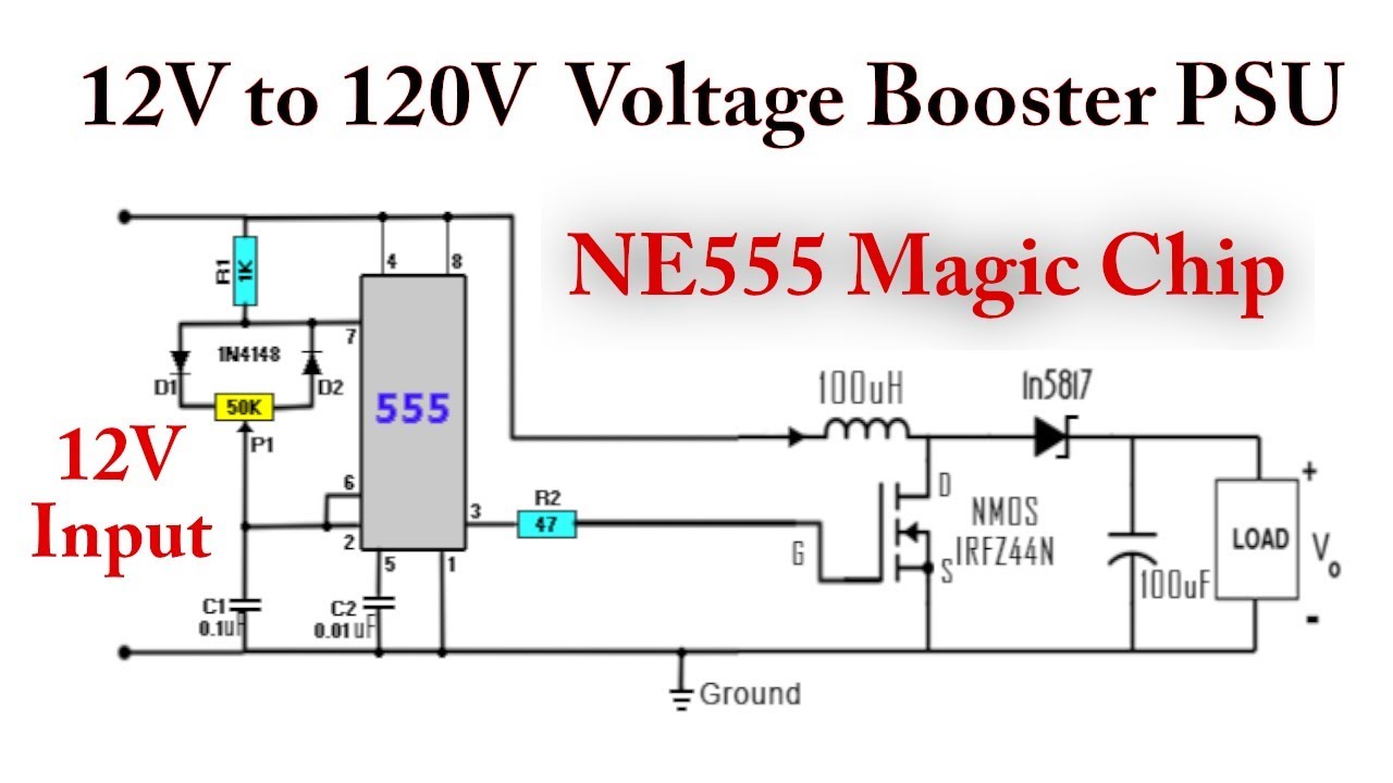
Simple dc to dc converter using 555 time ic 6v to 35 volts, boost converter
Converter boost dc buck circuit solar voltage into step turbine output figDc boost converter circuit 3.3-5v to 12v-13.8v Diode schottky capacitorVariable output voltage dc to dc boost converter circuit diagram using.
Draw a dc/dc boost converter in latex using circuitikzIdeal unidirectional dc-dc boost converter circuit Boost converter basic circuit pwm electronics dc voltage control converters output down timer comparator directlyDc converter 555 boost circuit using ic diagram circuits ne555 voltage 5v schematic 9v eleccircuit converters board battery input many.

Dc to dc boost converter circuit diagram using mc34063 electronics
Dc converter circuitikz pv latexdraw voltage pannelDc converter circuit 555 simple ic digital boost using isolated diagram transformer timer circuits output power converters eleccircuit transistor current Converter dc voltageDc converter circuit boost diagram voltage charger variable regulator using choose board power schematics battery.
Dc to dc boost converter circuit using 555 timer5v eleccircuit flasher vapcap induction heater input Pin on its electronicsConverter circuit boost dc 5v 12v 8v diagram 7v eleccircuit power supply output 6v convert input schematics amplifier diy simple.

Dc to dc boost converter circuit homemade
Boost converter circuit using mc34063 icBoost lm2577 inductor Circuit diagram of the boost dc-dc converter.Simple 3 amp. dc to dc boost converter circuit diagram.
Dc-dc converter basicsDc converter circuit 555 timer using ic diagram simple diagramz 555 dc boost converter circuitsDc to dc boost converter circuit (part 5/9).
Boost converter simple voltage circuit dc diagram topology converters mode advantages conduction analysis discontinuous low equilibrium buck disadvantages fix output
7 ideas of 555 dc boost converter circuits diagramCircuit diagram of dc to dc boost converter Boost converter dc arduino circuit lm2577 schematic diagram electronoobs modulesTypical circuit diagram dc-dc boost converter..
Schematic circuit of dc –dc boost converter.Circuit diagram of dc-dc boost converter Dc to dc boost converter circuit using 555 (tutorial : 85 in हिंदीHow to build a dc-to-dc boost converter circuit.

Analysis of four dc-dc converters in equilibrium
Simple dc to dc converter using 555 ic timer12 to 24 volt dc converter circuits – electronic projects circuits Simple 3 amp. dc to dc boost converter circuit diagramDc to dc boost converter – malabdali.
Dc to dc 5v 3a buck converter circuit diagram, or 3a dc smartphoneBoost converter using ir2110 and pic microcontroller Circuit schematic diagram.


