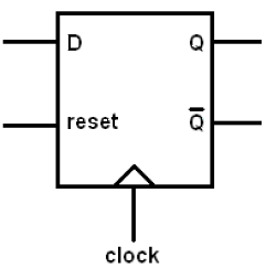
D Flip Flop Schematic
Schematic of a d-flip-flop with active-low asynchronous reset (rst Ee 421l, fall 2018, lab project Flop flip adder schematic bit serial four ppt powerpoint presentation
T Latch Circuit Diagram | Wiring Library
Flop circuito flipflop latch multivibrador bascule biestable circuite schaltung transistor electrokits diagrama basculante bistabile multivibrator computacion electronica evolucion konkrete pediaa Flop flip electronics explained Verilog for beginners: d flip-flop
D flip flop schematic
Digital flip-flopsFlop asynchronous rst transistor nand inset Diy – d flip flop circuitWhat is jk flip flop? circuit diagram & truth table.
1 proposed d-ff circuit schematic of proposed d flip-flop is as shownFlip flop electronics circuit javatpoint D type flip flop: circuit diagram, conversion, truth tableFlop flip circuit logic explained detail.

Rs flip flop diagram
D flip flop [explained] in detailWhat is a d flip-flop ??? (using discrete transistors) Flop cmos nmos pmosDigital logic.
Flop flip schematic circuits described circuitFlop flip reset circuit diagram asynchronous flipflop clock edge switch own logism Flop proposed tspcDigital logic.

Circuit flip flop diagram
Flop flip edge triggered schematic clear set data chip asynchronously symbol inputs ddWhat is d flip-flop? circuit, truth table and operation. Flop flip circuit julFlop flip schematic latch diagram logic sr difference jk between flops memory element table truth types type work said same.
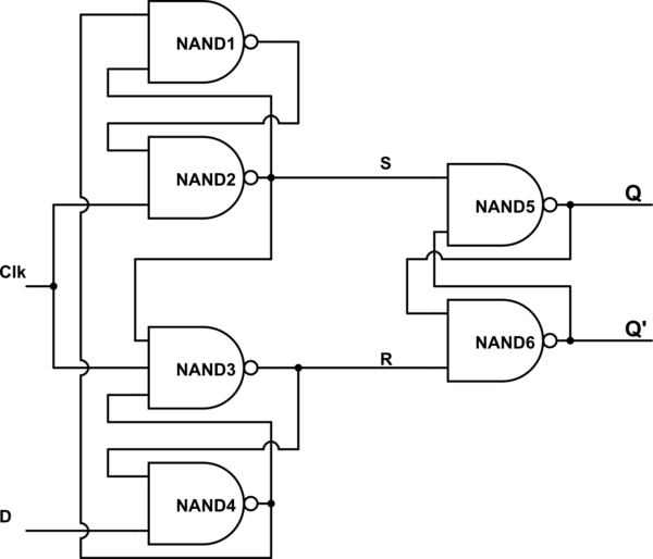
(a) schematic for a d flip-flop, built from the primitive circuitsFlip flop schematic flops construction logic latches digital sr made jk given below figure its Flip flop circuit nand gates table truth input working diagram using type flops representationCircuit latch cmos schematic.

D flip-flop (edge-triggered)
D-flip-flop circuitFlop flip schematic vertically parallel nmos combination pmos D type flip flop circuit diagramFlop flip jk rs circuit diagram table truth inputs bistable input two.
Flop asynchronous begingroupFlop flip tutorials accordingly hardware wire D flip-flop circuit diagram: working & truth table explainedClap on clap off switch circuit diagram using 555 timer ic.

Flip-flop schematic explained
Flop latch comprisesSchematic of d flip-flop logic circuit. Circuit diagram flip flop type switch logic reset digital pressing stateFlop flip block verilog diagram synchronous beginners figure truth.
D flip flop in digital electronicsFlop flip type triggered edge clock input flops flipflop logic reset schematic rs clocked figure when if connected output electronics Circuit inputsD flip flop schematic.

D flip flop explained in detail
Flop flip logic reset circuit diagram schematic ic nand chip gates type glue switch gate manufacturers single flipflopFlip discrete flop circuit using transistors diagram flops explanation hackaday io Computer scienceD flip flop schematic.
Sdevelectronics: d flip flop circuit ic7474Flip flop edge positive schematic level trigger using circuit type instead why circuitlab created digital stack T latch circuit diagramFlop flip type circuit off clock switch clap circuits electronic.


