Current Source Inverter Circuit Diagram
(pdf) voltage control of current source inverters Inverters dalibor Current equivalent
(a) voltage source inverter configuration; (b) current source inverter
Current source inverter circuit diagram (pdf) an over-voltage protection scheme with very fast response for Low-drop current source schematic circuit diagram
Inverter circuits rangkaian
(pdf) simulation of z-source inverter using maximum boost control pwmCurrent source inverter : circuit diagram and its advantages Current parallel capacitor 10khz induction thyristorInverter phase circuit three diagram project diy hub.
Basic circuit of current controlled voltage source inverterTransistors circuits Current source inverter : circuit diagram and its advantagesInverter circuit parallel igbt capacitor 2kw 10khz thyristor.

Inverter resonant
(pdf) comparison in performance between on igbt-based and thyristorPhase inverter conventional Inverter publicationElectrical video library: v/f control of induction motor.
Conventional single-phase current source inverter.(a) voltage source inverter configuration; (b) current source inverter (pdf) manual for solar technicianLoad resonant current source inverter circuits with two different.

Modified sine wave inverter circuit using ic 3525, with regulated
Inverter power circuit diagram medium cd4069 cmos supply inverters gr next circuitsCircuit diagram of load resonant current source inverter for induction Equivalent circuit diagram of single-phase current source inverterThree phase inverter circuit diagram.
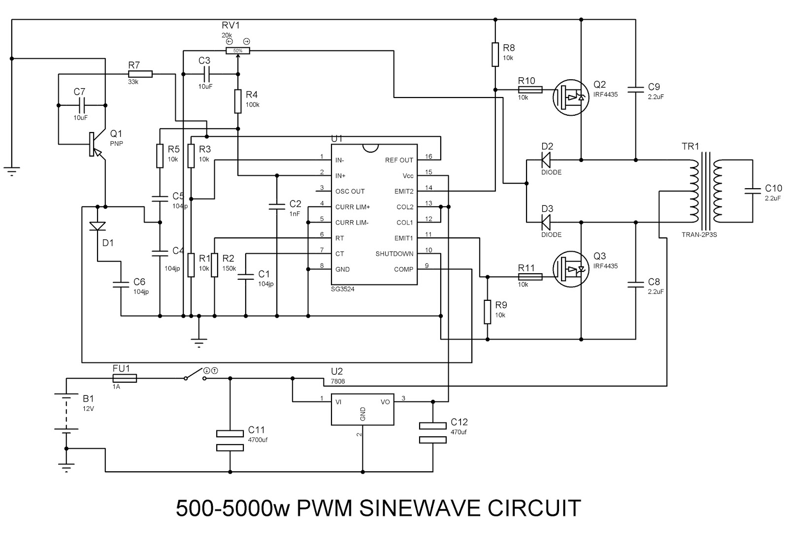
Inverter as high voltage low current source circuit diagramCurrent source circuit diagram schematic drop low sense determines r1 resistor using Three phase inverter circuit diagram – diy electronics projectsSinewave inverter circuit sg3524(pwm).

Medium power inverter circuit diagram
Simple inverter circuit using mje13007 transistors1, three phase inverter circuit Inverter phase circuit three mode conduction diagram degree dc dilip raja novCurrent source inverter.
Conventional single-phase current source inverter.Inverter circuits Inverter circuit sg3524 pwm sinewaveVfd inverter types.

Inverter source current boost maximum technique simulation pwm control using
(pdf) reverse blocking igcts for current source invertersInverter voltage current low circuit diagram source timer schematics ic using Source current inverter voltage load constant revolution electrical kept connecting input capacitor across sideSimple inverter circuit diagram.
Inverter resonant resistive crowbar capacitiveCurrent inverter circuit source diagram figure Electrical video library: v/f control of induction motorInverter current source circuit diagram power seekic reactive capacitive absorption exists filtering role load features.

Three phase inverter circuit diagram – diy electronics projects
Inverter circuit wave sine sg3525 using modified 3525 ic protection circuits low homemade diagram power board watt output projects electronicInverter current source vfd types circuit Sg3526 inverter circuit diagram / 500 w inverter circuit diagram cat 5Inverter electronic.
Inverter circuit simple diagram electrical wiring projects using easy diy power 12v dc electronic newcomers build ac spannungswandler 220v boardInduction heating resonant inverter circuit application load diagram current source voltage scheme csi prototype fed response protection fast very over Current source inverter ( csi )Inverter circuit.

Csi fed inverter converter currents inverters
Voltage inverter circuit source diagram induction motor control figure frequency variableCircuit diagram of current source inverter, r-l load with parallel .
.


