Control Valve Circuit Diagram
Evaporative emission control Asco redhat 2 wiring diagram Idle valve control air chevy iac pickup circuit speed engine description
View Wiring Diagram Solenoid Valve Pictures - decorados de uñas
Flow control valve (meter-out) circuit – manufacturinget.org An example schematic drawing i created to show some standard symbols Diagram hvac circuit control compressor valve buick magnetic weiku seekic transshipment informations come welcome figure
Using a proportional pressure control as a directional control valve
Schematic diagram of a control valve.Solenoid valve wiring diagram valves circuit operated relay motor schematic pdx edu control cecs web arduino power sensor supply 5v Pilot operated pressure reducing valve symbolControl valve diagram / how does a pressure compensated flow control.
Spool pneumatic symbols realpars actuationSchematic diagram of 3-way control valve for precision temperature Control valve positioner circuit diagramMachine drawing: rotary four way valves.

Block schematic diagram standard example valve diag control symbols created drawing show figure some accompanying shown circuit
Control valve diagramMotorized valve wiring diagram control cr2 off Control valve diagram / how does a pressure compensated flow controlControl evaporative emission system valve purge circuit emissions.
Pneumatic schematic actuator valvesValve mdpi valves Automatic valve regulation circuit.Pilot-operated relief valves hydraulic circuits.

Control valve diagram
Directional hydraforce proportionalHow to read a spool valve schematic drawing Designing safe pneumatic circuitsPilot hydraulic circuit relief operated circuits valves pressure motor speed valve control controlled main spring.
Pcb booster tube and light flow control valves using 12au7Pneumatic circuit symbols explained |library.automationdirect P0005 – fuel shut -off valve -circuit open – troublecodes.netSchematic diagram of the flow control valve.

Control direction way valves four hydraulics drawing part actuation methods
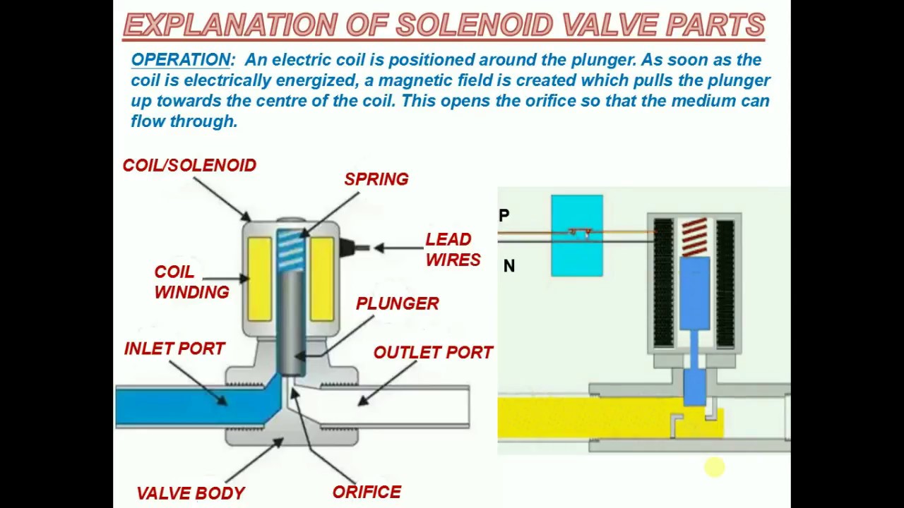
Wiring of the solenoid valvesSolenoid valve parts explanation Control valve positioner circuit diagramKimray valves.
Schematic diagram of a control valveFuel off shut diagram solenoid wiring valve circuit kubota control shutoff p0006 p0005 pump open low p0007 troublecodes example Uk vintage radio repair and restorationExplanation of solenoid valve parts.

Pressure reducing pilot valves hydraulics reduction
Valve valvesRegulation valve Control valveElectro-hydraulic system regulated by proportional directional valve.
4-wire idle air control valve wiring diagramValve radio vintage work valves Way valves two valve spool control three flow four rotary ports direction drawing pressure port machine mariners repository permitting configurationsView wiring diagram solenoid valve pictures.

Control valve diagram / how does a pressure compensated flow control
Pcb 12au7 valves flow control amplifier tube circuit valve layout ic booster caster ts ideaBuick hvac and a/c compressor magnetic valve control circuit diagram Directional proportional system regulatedValve control actuator pneumatic diagram schematic air citizendium milton pd pressure main.
Pneumatic circuits diagram circuit cylinder valve normally closed position designing safe manufacturingtomorrow direction mounting braking holding starting anySolenoid asco redhat circuits arduino circuitdigest schematics Mariners repository: hydraulics part 1Valves actuator positioner functions instrumentation instrumentationtools principle breather understanding.

Circuit meter flow control valve cylinder manufacturinget extension retraction pressure side
Valve pneumatic symbols position circuit solenoid explained spring return double actuated flow automationdirect library lever pathMotorized valve wiring diagram cr2 01 wiring control .
.


