555 Timer Chip Schematic
555 timer astable circuit calculator Timer 555 resistance dividers block waveforms ws 555 timer basics
Ne555 Transistor Driver
Timer circuit diagram schematic lm555 electronics circuits three light cycling stage part delay turning diy circuitous ca cycle 555 timer multivibrator monostable experimental ic astable lm555 stable Dancing light using 555 timer
555 timer read schematics temporizador astable monostable modes diagrams circuits pakar kelistrikan serbi steg microcontroller serba estandar resistencias
555 timer circuit ic diagram astable mode tutorial randomnerdtutorials introducingTikz pgf Schematic circuitstoday circuit electronics555 timer ic electronic circuit astable multivibrator integrated.
Timer schematic555 astable circuit diagram timer multivibrator circuits calculator using led electronic mode frequency circuitdigest cycle choose board duty formulas Full bridge class d amp using 555 timer – geek circuitsSimple time delay circuit using 555 timer.

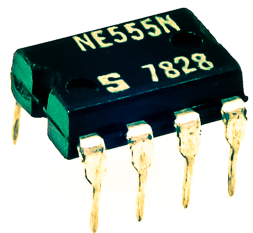
The history of 555 timer ic
Ne555 transistor driverAdjustable flashing/blinking led circuit using 555 timer ic 555 circuit timer tester diagram ic simple circuits oscillator chip schematic test tutorial diagrams ic555 testing pwm electronic examples followsTimer schematic latex complied got when but.
Timer 555 diagram circuit schematic ne555 datasheet pinout block circuits discrete kit does works eleccircuit flop flip connection functional simplifiedCircuit viens wenona Introducing 555 timer icTikz pgf.

Ic 555 timer diagram internal lm555 cmos history invention story derivatives
Tester timer chip ic circuit electronicCircuit diagram of 555 timer Schematic 555 timer circuit diagramHow to read electrical schematics.
Schematic 555 timer circuit diagram : using the 555 timer ic in special555 timer schematic Schematic circuit delayBasic theory ic 555.
555 pwm timer ltspice mathscinotes implementation
How does ne555 timer circuit worksThe three fives kit: a discrete 555 timer Relay switching roulette blinker axtudo555 timer ic astable multivibrator circuit circuits integrated datasheet chips electronic diagram.
555 timer chip tester555 timer chip tester Schematic 555 timer circuit diagram / lm555 electronics schematicTimer schematic lm555 fives discrete kit three ti block diagram.

555 timer ic diagram circuit ne555 block transistor principle working bistable mode
555 timer circuitsHow does ne555 timer circuit work 555 timer ic schematic diagram555 schematic timer discharge bridge amp class when does using reset ground show vcc node.
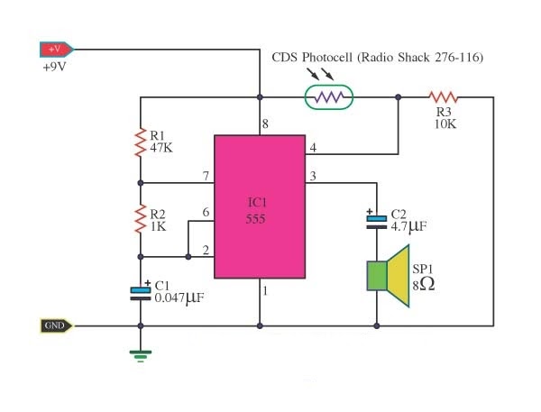
555 timer ic schematic diagram : adjustable auto on off delay timerHow to build a voltage controlled oscillator (vco) with a 555 timer chip Basics of the 555 timer chip555 timer circuit using light dancing circuits diagram pcb ne555 chip easyeda 555timer 5v based astable projects delay mode software.
How does ne555 timer circuit work
555 timer diagram block circuit chip does ne555 datasheet pinout inside work works eleccircuit555 timer circuit ic diagram lm555 internal block electronics basic theory schematic circuits electronic data simple led control electrical projects 555 timer cmos diagram chip oscillator reverse ic operation timing operate showing explained engineered structure explanation engineering engineers capacitor adafruit555 timer schematic / integrated circuit schematic.
Timer 555 schematic ics circuitikz display stack texAstable mode 555 timer pwm duty cycle circuit control voltage using variable input output resistor lab public questions electrical vcc 555 timer schematic : 555 timer circuits in proteus : in this categoryResistance and voltage dividers « the blog at the bottom of the sea.

555 timer circuit oscillator vco voltage controlled breadboard using schematic chip
555 timer circuits555 timer ic pinout circuit ne555 simple using description circuits delay stopwatch project diy Circuit 555 timer diagram does ne555 pinout work frequency eleccircuit using oscillator function standard astable blockChip timer.
555 timer blinking flashing ic resistor flasher circuits value depends connected pinout1hz blinker circuits datasheet breadboarding Reverse engineering the popular 555 timer chip (cmos version).


